On display at the October 2009 Tokyo Motor Show
The Center for Advanced Sound Technologies of Yamaha Corporation (Headquarters: 10-1, Nakazawa-cho, Naka-ku, Hamamatsu, Shizuoka, President: Mitsuru Umemura) and Yamaha Motor Co., Ltd., performed acoustic design work for the engine of the Lexus LFA, which will be displayed at the 41st Tokyo Motor Show that begins on October 23. Yamaha Motor assisted in developing the engine for this sports car. The goal of the acoustic design project was to generate the dramatic and exciting acoustic properties that people expect of mass-produced super sports car like the Lexus LFA.
The Lexus LFA and its engine will be on display at the Lexus booth at the 2009 Tokyo Motor Show, and the prototype engine will be shown at the Yamaha Motor booth.
The acoustic designing concept
The objective of this acoustic design was to utilize sound as a medium that can achieve a direct link between the driver and the vehicle. To accomplish this goal, Yamaha and Yamaha Motor decided to base the design on the following two goals.
- Create an engine sound that reacts instantly to even delicate alterations by the driver in the vehicle’s operation.
- Effectively convey all of the high-grade engine sound to the driver.
This approach was based on Yamaha’s expertise in creating relationships between performers and musical instruments to give the perfomers the full enjoyment of playing an instrument.
When playing a musical instrument, performers hear the delicate changes in volume, tone, and nuances that they produce themselves. Hearing these subtle changes allows performers to make instant revisions as they play the instrument. For these performers, access to high-quality audio feedback is vital to achieving the best possible performance. In this case, sensing the direct feedback of the musical instrument is what provides the performers with the enjoyment of playing an instrument.
<Chart>
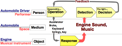
Figure 1: The important interactive loop linking a “musical instrument, space, and performer” and “engine, body, and driver”
Feedback is equally important when driving an automobile. In this case, feedback refers to how the vehicle responds to the driver’s actions. In a super sports car like the Lexus LFA, providing a high-grade engine sound that changes with even a delicate operation by the driver can contribute directly to the enjoyment of driving.
We believe that sound is a valuable means of communication between the driver and vehicle. Accurately passing on high-grade engine sounds to the driver makes it possible to feel the vehicle’s condition and instantly take the next minute action that is required.
This is how sound can be used to establish and enhance an interactive loop between drivers and automobiles. Our goal was to make the experience of operating a super sports car even more exciting and enjoyable.
Features of the acoustic design
To perform this acoustic design, we viewed the engine as the generator of sound and the automobile as a medium for conveying sounds from one place to another. We then came up with an idea for how to achieve a smooth interaction between drivers and vehicles, and it was adopted.
The Lexus LFA is powered by a 10-cylinder engine that was co-developed by Yamaha Motor and has an even firing interval. Only physical acoustic methods were utilized to give the driver a direct sensation of this engine’s characteristics. There is no electrical or electronic sound processing. As a result, sounds that reach the driver are clear, dynamic, and smooth.
Furthermore, this acoustic approach has two advantages. The first is the ability to hold down noise under normal driving conditions, such as in a city. The other advantage is an outstanding response in engine sound during strong acceleration.
1.Acoustic design using the engine as a sound generator
We studied and used the surge tank (note 1) as part of the intake system to radiate the sound. The vibration mode of this tank was controlled by optimizing thickness, rib configuration, and other aspects of its design. When accelerating at an engine speed of about 3,000rpm, the driver hears a powerful harmonic sound structure centered around 250Hz, which is the primary component of combustion tone (note 2). At a high engine speed of about 6,000rpm, the harmonic sound structure is centered around 500Hz. This produces a sound that is rich and smooth. For even higher engine speeds, we further increased the number of high frequencies to create a sound that clearly reflects how the engine speed is climbing.
Note
- The surge tank in the air intake system has a fixed capacity that is used for the purpose of preventing air intake pulsing and interference. This helps maintain a uniform flow of air to each cylinder.
- The primary component of combustion tone is frequencies having the same cycle as the engine’s combustion system. This is the primary component of the frequencies that give an engine its distinctive sound.
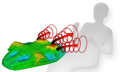
Figure 2: Image of the surge tank vibration mode and sound radiation image
2.Acoustic design using the automobile to convey engine tone
Yamaha and Yamaha Motor proposed equipping the automobile with a composite sound conveyance device (note 3). This device maintains balance in the volume and frequencies of sound from the engine while effectively guiding sound radiated by the surge tank into the vehicle’s interior. Using this method directly passes on sound from the air intake while holding the volume of engine sound to a comfortable level. Furthermore, the driver can enjoy sound with a spatial quality that is an integral part of the vehicle.
Note3
Path for conveying engine sounds and functions of parts The composite sound conveyance device comprises the following four parts.
- Main path: The main path is a duct that efficiently feeds sound radiated by the surge tank into the vehicle’s interior. Using this duct ensures that a sufficient volume of engine sound will reach the driver.
- Dashboard opening: This opening allows only engine sound to pass; it is designed to block odors and moisture and maintain the airtightness between the engine room and the interior of the passenger compartment of the vehicle.
- Sub-path: This side path is a sound conveyance duct with a primary resonance frequency of 500Hz. The dragon eye adds a feeling of richness to the somewhat rough air intake noise. Sounds that are mainly in the middle and high frequencies reach the driver from the right and left while expanding outward.
- Sound adjuster panel: This panel adjusts the volume of noise from the air intake system and the frequencies so that the driver hears a pleasant, high-grade air intake sound. The final effect is a sound that emanates from around the driver’s feet and envelops the driver.

Figure 3: Configuration of sound conveyance device
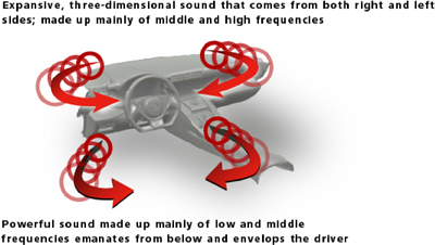
Figure 4: How sounds enter the vehicle’s interior
3.Design created using a newly developed engine sound processing tool
Successful acoustic designing requires the establishment of a common goal for all participants at the initial stage of development. For this project, we developed an engine sound processing tool. With this technology, we were able to alter the engine sound on a real-time basis under actual driving conditions.
Conventional acoustic designing is performed primarily by examining automobile sounds while the vehicle sits still in a testing chamber. However, this approach does not allow monitoring how a vehicle responds to actions by the driver. With the newly developed tool, we could check actual vehicle responses to our operations under real driving conditions with an interactive loop. We used the tool from the beginning of the development process. Evaluating and studying sounds under actual driving conditions allowed the development team to complete the acoustic design while aiming for the same goal.
Collaboration between Yamaha and Yamaha Motor
These two companies, which share the Yamaha brand, collaborate in many ways. Yamaha created the design for the Dolsa Wind concept electric motorcycle that Yamaha Motor unveiled at the 2003 Tokyo Motor Show. In 2007, Yamaha handled the interior audio design for Yamaha Motor’s Luxair motorcycle that made its debut at the Tokyo Motor Show. In October 2008, Yamaha and Yamaha Motor held a joint design exhibition called “Keys” in Tokyo’s Harajuku district to highlight the design skills of the two companies.
Yamaha’s acoustic design expertise
As part of our devotion to creating outstanding musical instruments, we believe that the spaces where music is heard are just as important as the instruments themselves. In all, we have created acoustic designs for more than 200 halls and other public facilities over a period of more than three decades. Backed by know-how concerning architecture and electrical acoustics, our acoustic design technology can meet a diverse spectrum of requirements. Our use of the same technology to fabricate musical instruments and audio equipment is key factor that differentiates our products from those of competitors.
Performing R&D for many years in the fields of musical instruments, audio equipment, and acoustic spaces gives Yamaha a wealth of technologies and knowledge. We use this know-how to develop products and in a broad array of other activities involving sound. Our participation in this acoustic design project is one illustration of the breadth of activities.
For further information, please contact
Public Relations Group
Corporate Communications Division
YAMAHA CORPORATION
17-11, Takanawa 2-chome, Minato-ku, Tokyo 108-8568, Japan
- Telephone: +81-(0)3-5488-6605
- Facsimile: +81-(0)3-5488-5063
![]() Visit Yamaha's website at
Visit Yamaha's website at
http://www.yamaha.com/